The McDonald truss
Approximately 90 McDonald type timber truss bridges were built between 1886 and 1893, and four remain. Due to the very large timbers included and the fact that they were not intended as permanent structures, deteriorated timbers are very difficult to replace and remaining examples of this type of truss tend to have been heavily modified prior to restoration.

The historical context which drove the design of the McDonald truss was similar to the Bennett truss in that large, long, quality hardwoods were still plentiful and permanent stone or iron bridges were not considered economical. The changes in design stem from the extensive timber testing at the University of Sydney in 1886 and the increasingly heavy vehicle loads. McDonald updated the standard timber truss design for the new heavier design loads (a distributed live load of 4kPa and a traction engine weighing 16 tons) based on new information. McDonald did not greatly change the overall shape of the truss (see comparison below).
The 1886 testing enabled McDonald to modify the standard design to accommodate higher vehicular loads, as described by Percy Allan, commenting on the Bennett type trusses:
“Although this type of truss has for many years carried the traffic without accident, yet in view of the increase in settlement and the greater risk of the structures being subjected to heavier loads, it was thought desirable in 1886 to adopt [the McDonald truss design]… These structures were designed for a distributed live load of 84 lbs. per square foot (4 kPa) of roadway and a traction engine weighing 16 tons…”[1]

 Source: Drawn by Jack Pulczynski for Amie Nicholas.
 The first part that required strengthening for the heavier loads was the bottom chord. Percy Allan helpfully drew a sketch comparing bottom chords in the first three truss types (see below).
- FIG 1 shows details of Bennett’s (Old PWD) truss, consisting of a laminated timber bottom chord with three rows of laminates and a small metal fish plate at each joint location, designed not to carry any loading, but to provide a template to ensure correct bolting.
- FIG 2 shows the details for the McDonald truss, which consists of a laminated timber bottom chord with four rows of laminates and two large central metal splice plates, designed to share the load because this truss type was designed for heavier vehicles.
- FIG 3 shows the details for the Allan truss, which consists of a double timber bottom chord with a gap between each element and a direct tension connection made up of four wrought iron plates with metal shear keys riveted to them and then these plates bolted to the timber.
 Source: Percy Allan, Timber Bridge Construction in New South Wales, Royal Society of NSW, 1895.
 Because McDonald’s bottom chord was considerably wider than Bennett’s, McDonald had to modify the principals to fit. While all the timber truss road bridges make use of cast iron shoes, Bennett showed the most care in making these shoes a positive aesthetic feature. Bennett’s shoes were specifically designed to frame the truss, both aesthetically and structurally, with the top chords, bottom chords and principals all being of the same dimensions, and all being the most critical structural members, these shoes ensured strong connections as well as aesthetic highlights. McDonald’s change in bottom chord required a change in principals and shoes, so McDonald returned to something which Bennett had tried much earlier, the splaying of the principals at the base to provide stability. Because McDonald introduced the splayed principals for his truss, he no longer required the timber sway braces which were a feature of the Bennett truss, so he replaced these with far more slender metal sway braces. These metal sway braces were not designed to provide lateral support to the top chord, but only to resist excessive sway or vibration when heavy vehicles crossed the bridge.
 Source: Amie Nicholas.
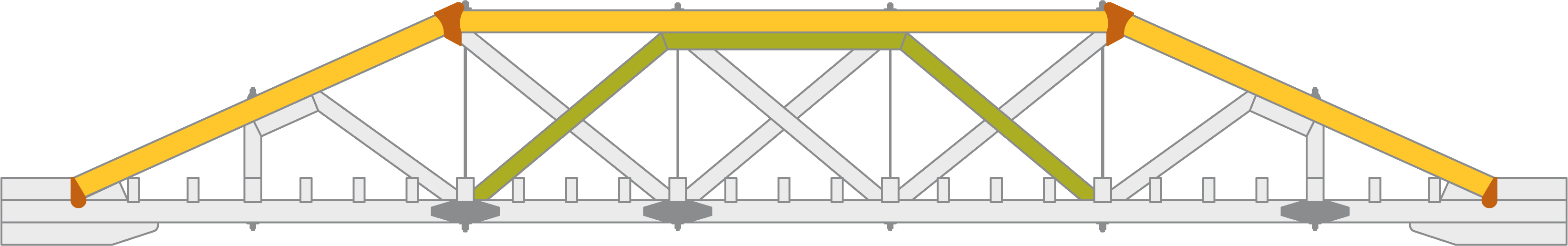
 While Bennett had maximised the use of large section timbers to manage shrinkage and warping of timbers by applying the structural system of an arch within an arch (see comparison below with green arch highlighted within the yellow arch), McDonald now had better information on the capabilities of the New South Wales hardwoods, and so he managed shrinkage and warping of timbers by using double timbers bowed around timber spacers and by providing metal wedges at the bases of diagonals to take up the slack (metal wedges are highlighted green in the McDonald truss below). With these changes, McDonald also did away with the shoes at the base and introduced new cast iron shoes at the intersections of the diagonals and top chords (the cast iron shoes of each truss highlighted in red).

 Source: Sketches drawn by Jack Pulczynski for Amie Nicholas, photograph by Amie Nicholas.
 In common with the Bennett truss, the McDonald truss was constructed as a temporary bridge and therefore was not designed for ease of member replacement. The primary cross girders form part of the truss (with the diagonals bearing against them and the tension rods bored through them) and are therefore exceedingly difficult to replace. The difficulty is exacerbated by the fact that the primary cross girders are also notched into the bottom chords.
A unique and sometimes problematic feature of the McDonald truss is that none of the diagonals are fixed to the top or bottom chords. At the top chords, they simply fit into a recess in the cast iron shoes, and at the bottom chords they fit into a recess in the laminated timber bottom chords. In all of the later timber truss bridge designs, there was a bolted connection between the diagonals and the shoes at both the top and bottom chords, and in the earlier truss, there was a direct bolted connection between the loaded diagonals and the top chords.
The top chords consist of single large cross-section long sawn timbers (similar to the Bennett truss design). The later truss types (Allan, de Burgh and Dare) used not only paired members for the top chords, but also shorter lengths of timber with splices to make up the length.
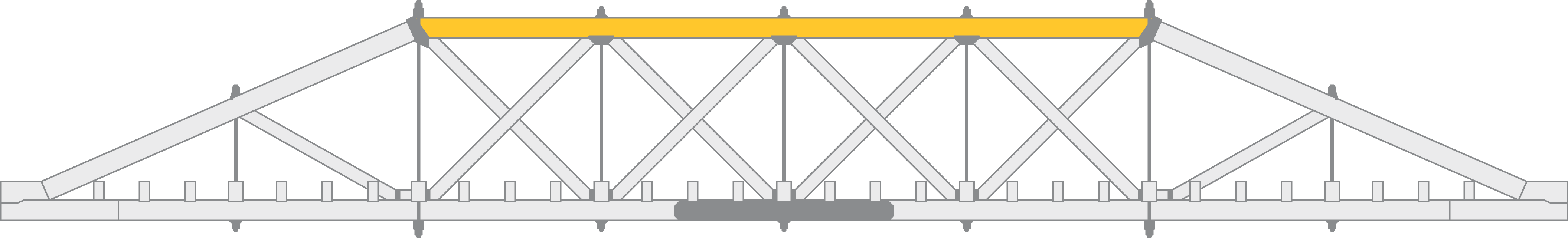
Principals (in yellow below) in the McDonald truss are significantly longer than diagonals (a feature shared with the Bennett truss), with a diagonal timber prop (in green below) approximately half way along the length and a vertical tension rod (in red below) also at that location. The principals are splayed and are the only members in any timber truss bridge where the timber spacers are critical structural components in the member.

Principals are supported at the base on long timber butting blocks with no shoes. Butting blocks are bolted to bottom chords and notches with timber shear keys transfer the loads.
Bottom chords consist of four rows of sawn timber laminates bolted together. Joints for all laminates occur only at secondary cross girders, and very long metal splice plates are provided at the centre of each span. The laminated timber bottom chords are continuous over piers. Every bolt location and length of timber was carefully detailed in the original design provided to maximise strength for the high loads, requiring timbers in excess of 16 m in length.
 Source: TfNSW Plans Management System annotated by Amie Nicholas.
 McDonald trusses had two, three or four counterbraced central panels, depending upon span length. All three standard span lengths for McDonald trusses remain (65’, 75’ and 90’).

The diagonals of the McDonald truss consist of double and single diagonals counterbraced together. In the figure above, the double diagonals are highlighted in yellow and the single diagonals are highlighted in green. Each diagonal is recessed into a cast iron shoe (highlighted in red above) at the top and bears against the bottom chord and wrought iron wedges at the base. Each double diagonal has timber spacers each end.

Single vertical wrought iron tension rods (green above) are installed through holes drilled in the top and bottom chords. Double vertical wrought iron tension rods (orange above) are provided at each end of the top chord, with iron saddled connections top and bottom. All tension rods are of the same diameter, with only the lengths varying for the different types.
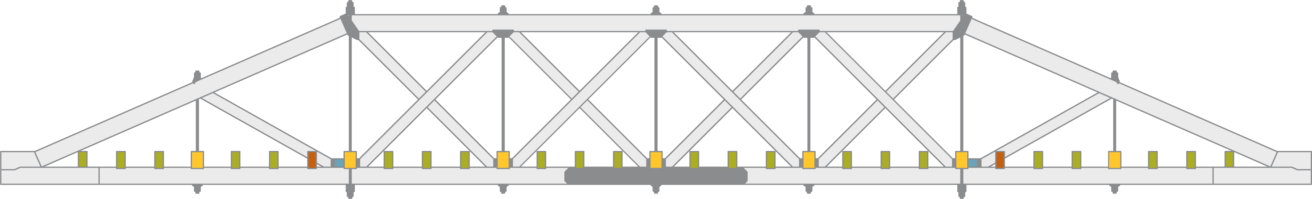
Cross girders in McDonald trusses are closely spaced and carry diagonal decking similar to the Bennett truss. The primary cross girders (highlighted in yellow above) form part of the truss, whereas the secondary cross girders (highlighted in green above) are of smaller cross-section and are provided only to support the diagonal decking. Two of the secondary cross girders (highlighted in red above) have considerable notches cut out of them to accommodate the principal prop. This feature is unique to the McDonald truss. Bennett in his truss had avoided such notching, but in so doing had introduced eccentricity of load paths (ie. the centrelines of members did not all intersect at a single point at connections). McDonald did away with eccentricities, but this required that two thirds of the section of these secondary cross girders were removed, and it also necessitated the timber packing (highlighted in blue above) to support the principal diagonal prop.
References
[1]Percy Allan, Timber Bridge Construction in New South Wales, Royal Society of NSW, 1895, p 1.