The Bennett truss (sometimes called Old PWD truss)
Approximately 150 Bennett type timber truss bridges were built between 1858 and 1886, and two remain today. The Bennett trusses are examples of innovative and practical engineering in a time when large long timbers were readily available and vast numbers of bridges were being built, but budgets were tight and skilled workmen were few. The Bennett trusses were not designed as permanent structures because the required routes were very likely to be diverted by circumstances impossible to anticipate. For these reasons, any deteriorated timbers are difficult to replace so the bridges tend to have been heavily modified.

The primary characteristics that distinguish William Christopher Bennett’s designs for the Bennett type timber truss bridges from other timber truss bridge types are examined here.
The top chords and end principals of a Bennett truss consist of single large cross-section long sawn timbers, all of the same cross-sectional dimensions. The McDonald truss also has a single solid top chord, but the single solid principals are unique to the Bennett truss. The later truss types (Allan, de Burgh and Dare) used not only paired members for the top chords, but also shorter lengths of timber with splice connections.

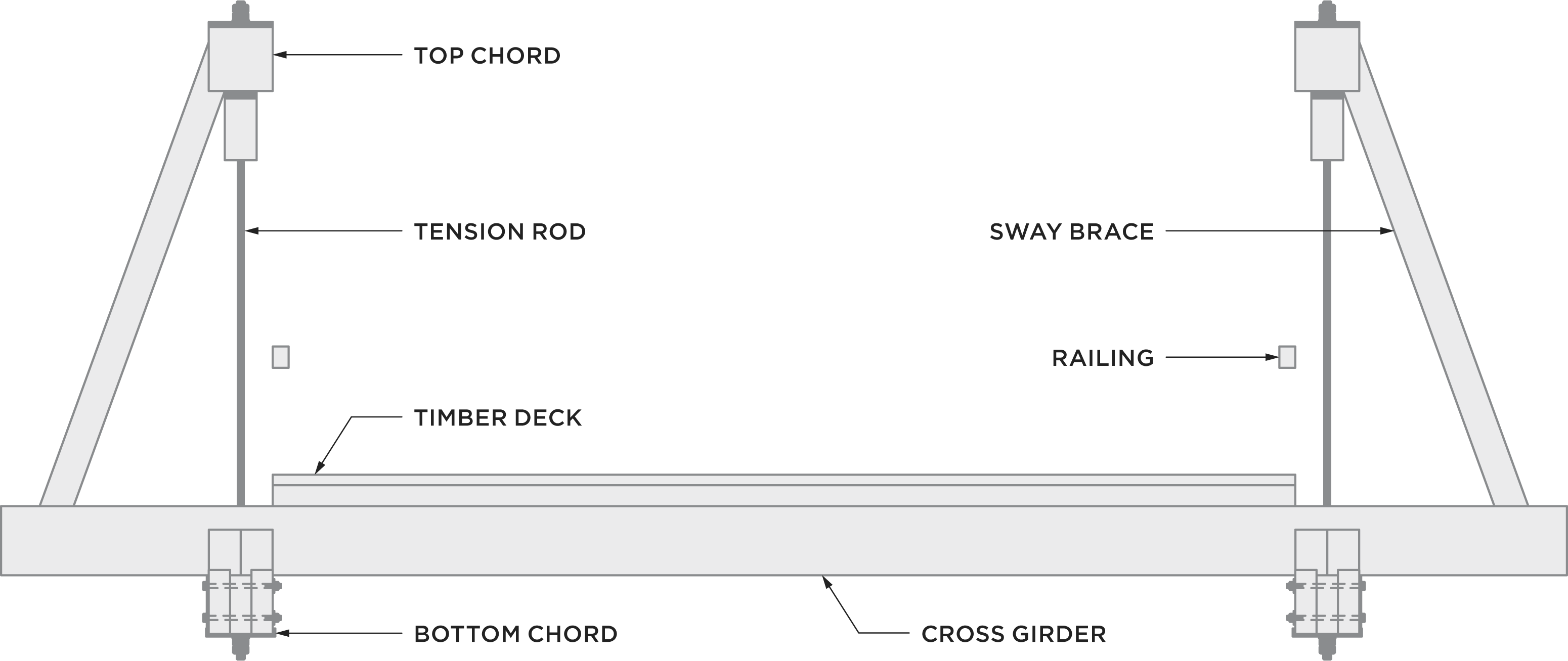
Principals in the Bennett truss are significantly longer than diagonals (a feature shared with the McDonald truss), with a vertical timber prop approximately half way along the length and a vertical tension rod also at that location to support a primary cross girder. A timber spacer separates the vertical timber prop from the diagonal timber prop. Although the McDonald truss also has a diagonal prop, the vertical timber prop and spacer are unique to the Bennett truss.

Principals are supported at the base by timber butting blocks. Butting blocks are bolted to the bottom chord, and timber shear keys or notches are used to transfer the loads. There is a tear-drop shaped cast iron shoe provided between the principal and the butting block, which always has this unique shape. There is another cast iron shoe at the top of the principal connecting the principal, the top chord, a tension rod and some counterbracing. The shape and the details of this top shoe were modified for different Bennett truss designs. The use of shoes exclusively at ends of principals is unique to the Bennett truss. McDonald had shoes only at the top chord (for both principals and diagonals) and none at the base of the principals, whereas the later truss types (Allan, de Burgh and Dare) had many more shoes.

Timber sway braces (labelled below) are provided at all top chord panel points to laterally support the top chord and to resist sway of the trusses under vehicular loads. The use of timber sway braces is unique to the Bennett truss. Also unique to the Bennett truss is the design of these members, detailed in order to provide lateral support to the top chord.
Bottom chords consist of three sawn timber laminates bolted together to form the same cross-section as the top chord and principals. Joints for all laminates occur only at panel points, and small metal fish plates are provided at each joint. The laminated timber bottom chords are continuous over piers and are common to the Bennett and McDonald trusses, but the Bennett truss always had three rows of laminates and the McDonald always had four (with long central metal splice plates at mid-span) because McDonald was designing for heavier loads. The fish plates in the bottom chord of the Bennett were not designed to carry any load (as is clear from the fact that they exist even when the internal laminate is the only discontinuous laminate) which sets them apart from the McDonald and Allan designs. The fish plates were a clever innovation by Bennett to provide a bolting template to ensure the correct bolting arrangement was provided at all the joints, and are different shapes for different span lengths.

Bennett trusses had two, three or four counterbraced central panels, depending upon span length. Only two Bennett trusses remain (70’ and 100’), and both have three central panels.
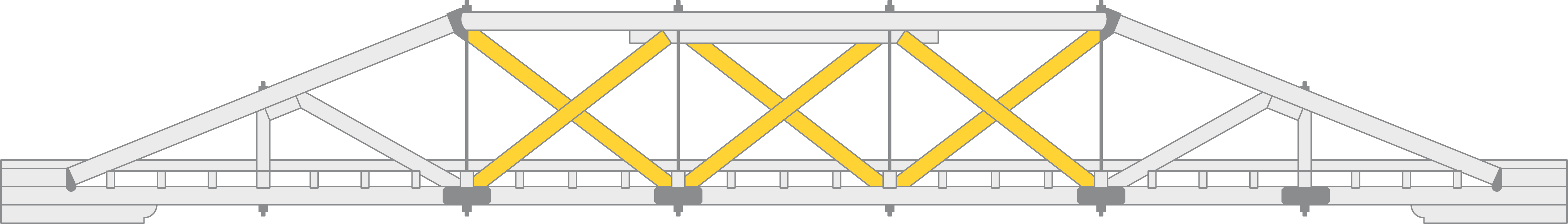
For trusses with three central panels, the middle panel has a double top chord. Longer spans (e.g. Clarence Town) have the double top chord extending beyond the panel points, whereas others (e.g. Monkerai Bridge) have the double top chord stopping neatly at the panel points.

Single or double vertical wrought iron tension rods are installed through holes drilled in the top and bottom chords. Larger diameter tension rods are generally provided towards the ends of the top chords where stresses are higher than the smaller tension rods towards the centre of the span. Cross girders are generally (not always) closely spaced, carrying diagonal decking.