The Allan truss
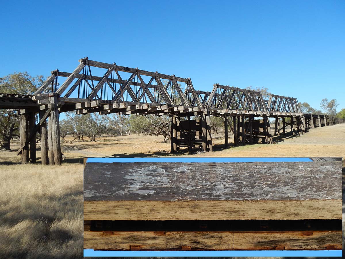
Approximately 100 Allan type timber truss bridges were built between 1893 and 1929, with 10 to be retained under the Transport for NSW Timber Truss Bridge Conservation Strategy. The historical context which drove the design of the Allan truss was the increasing difficulty in obtaining large timbers. Allan introduced two important innovations. The first was the detailing of timbers to enable the replacement of deteriorated timber, giving his timber bridges the same life expectancy as metal bridges. The second was his splice connection in the bottom chord which was stronger than previous bottom chord connections. Many Allan and Dare truss bridges were constructed to replace Bennett or McDonald trusses, sometimes reusing the original foundations if those foundations were constructed in iron or masonry.

The Allan truss was the third in a five-stage design evolution of NSW timber truss bridges. Allan’s design was driven by financial and resource constraints. Money was scarce after the bank crashes in London in 1890 and in Australia in 1892-3.[2] Labourers and supervisors were being laid off and engineers (such as McDonald) retrenched or forced into early retirement. Large timbers were increasingly scarce and expensive and sometimes unobtainable. Earlier designs were not intended as permanent structures since the road alignments were still being developed, so they were expensive to maintain, and often had to be completely replaced.[3]
The focus for Allan in his design was the use of small section timber designed for maintainability. Allan introduced two important innovations in his timber truss bridge design. The first and most critical innovation was the detailing of timbers to enable replacement. This meant that the timber bridge would be more economical than an equivalent “permanent” metal bridge, not only for initial construction, but also over the whole life of the bridge.[4]
The design philosophy of the architect, landscape gardener and poet, Thomas Pope applied:
When Time, with hungry teeth, has wrought decay,
Then what will sceptics be dispos’d to say?
Why, “down the Bridge must fall, without repair,
And all the author’s pleadings will be air.”
Not so, he’s better arm’d than you’d expect,
For nought can bring to ruin but neglect;
A means provided, which can never fail,
To keep up strength whate’er the B ridge may ail;
Each log of wood, where’er its station be,
Is safely shifted for a sounder tree…[5]
Allan explained in less poetical terms how he saw it working for his timber truss bridge design:
One of the features of the new type of truss is that any member can be renewed without staging from below, a matter of importance when deep gorges or fast running streams have to be crossed. Briefly stated, the top and bottom chords being in two pieces, the suspension rods (by which Allan means tension rods) are removed and re-arranged so as to throw the whole weight on one flitch; there being no strain on the remaining flitch, any member of the top and bottom chord can be replaced with sound timber; and by slacking the suspension rods and inserting temporary struts, any of the braces can be renewed, whilst the renewal of the cross girders is obviously a simple matter.[6]
While it is true that replacement of timbers in the Allan truss is considerably simpler than replacement of timbers in the Bennett or McDonald trusses (which Allan described as something like a Chinese puzzle), it was not achieved quite in the way which Allan had anticipated (nor as easily as Allan had claimed in some of his papers).[7] As early as 1904, Dare reported that, “in almost every case the timber lower-chord has been the first member of the truss to fail, and the flitches, being in tension, are very difficult to replace”.[8] The flitches of the top chords also are more difficult to replace than implied by Allan’s enthusiastic statements. Because the flitches of the top chords are bowed to prevent warping and twisting, a single flitch is not really able to keep its shape and take the load without the other. Luckily for Allan, other engineers invented methods of temporary support to replace the timbers.
 Source: Percy Allan, Timber Bridge Construction in New South Wales, 1895.
 Allan’s second innovation was his splice connection in the bottom chord which was much stronger than previous bottom chord connections and did not require such long lengths of timber. Allan’s splice connection was subsequently used by the railways in NSW and as far away as the United States.[9] The bottom chord splices being so critical, Allan tested the full-size joint in a machine specially designed for the purpose. The machine consisted of a heavy ironbark frame and large hydraulic jack. In the three tests conducted, failure occurred by the shearing of the bolts and of the timber between the notches, the recorded results showing an ultimate strength of 151, 160 and 182 tons (153, 162, 185 tonnes) respectively, the size of the timber flitch was 13” x 6” (330 x 150 mm) and the steel plates 12¾” x ½” (324 x 12 mm).[10] Warren noted that for ironbark timber, the shearing resistance along the fibre is generally about 2,000 lbs. per square inch (14 MPa).[11]
 Source: Amie Nicholas.
 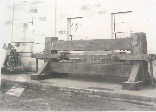 Source: Otto Cserhalmi, Pyrmont Bridge Conservation Management Plan, 2006, p 59.
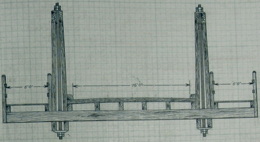
 Allan described his bottom chord innovation as follows: [12]
The bending stress in the bottom chord of the new truss having been eliminated by the omission of intermediate floor beams (ie. cross girders), only a direct stress has to be provided for, resulting in a considerable reduction in the sectional area of the bottom chord, which consists of two flitches 12” by 5” (304 x 127 mm) placed 6 inches (152 mm) apart, thus being always accessible to the brush, and permitting of the renewal of these important members; again the longest flitch is only 36 feet (10.97 m), a length easily procurable.
Perhaps the most important connection in a timber truss is the bottom chord joint… As the two flitches in the bottom chord are independent of one another, the whole stress in each flitch has to be taken by the two 12" by 5/16" (304 x 8 mm) wrought-iron plates placed on either side of the beam; on each of these plates four wrought-iron strips 12" deep by 1¾” wide by 1" deep (304 x 45 x 25 mm) are riveted; these strips are let tightly into the timber and are designed to take up the whole of the stress, and, as the stress in each flitch is 31.18 tons and there are four strips giving a total bearing area of 48 square inches, the crushing strain is only 0.65 tons per square inch, thus giving a factor of safety of 7¼ against crushing, whilst for shearing along the grain a minimum factor of 15 is provided.
Following American practice, the bolts passing through cover plates are not in any way relied upon, being simply provided to keep the plates up to their work, however as the bolts had to be provided the author determined to obtain the benefit of them, and arranged for the bolts to be turned and passed through drilled holes in the plates.
It is undeniable that Allan’s bottom chord tension splice was a very clever innovation, achieving a stronger and more economical timber bottom chord than the previous timber truss designs. However, this did not come without a cost. The earlier laminated timber bottom chords did not fail suddenly without warning but tended to stretch and sag over time until they were replaced. Allan’s new bottom chord, however, would tend to simply snap suddenly under a heavy load, and sometimes this would cause the entire truss to collapse. Though Allan sought to improve durability over the previous designs, his bottom chord splices were still subject to accelerated deterioration, especially where splices were too close to panel points.
While Bennett sought to avoid the limelight, and McDonald certainly seemed not to seek popularity, Allan was vocal in coming forward and announcing his achievements to the world.
The report to the NSW Legislative Assembly for the Year 1893-4 details Allan’s innovations:
The type design for truss bridges in use since 1884 [sic, 1886] has been superseded by a truss of more modern design, the principal features of which are: the use of marketable lengths of timber, the adoption of open chords and braces always accessible to the brush, and the ease with which any defective timber can be replaced. In each of the new 90-feet spans there is a saving of 450 cubic feet of timber, while the trusses are capable of carrying 10 feet more roadway [sic, two 5’ footways] than in the old type of truss, thus affording greater travelling facilities at reduced cost. Not only is there a saving in materials in the new type of truss, but a considerable saving is effected owing to the shorter lengths of timber employed and the greater ease in framing together. Altogether the saving effected by the adoption of the new type of truss bridge is on the average about 20 per cent.[13]
Allan here compares his design loads with previous truss types:
- There is no remaining record of Bennett’s design load for the Old PWD, other than the fact that it was less than the design load for later timber truss bridge designs.
- The 90’ McDonald truss was designed for a 16 tonne traction engine plus a distributed live load of approximately 50 tonne (probably for cattle).
- The 90’ Allan truss was designed for a 16 tonne traction engine plus a distributed live load of approximately 75 tonne (designed over a wider deck area).
The reason for this higher design load in the Allan truss is quite interesting. Allan designed his truss to accommodate a central roadway and two footways on the outside of the truss (one on each side) although this configuration was never actually used in an Allan truss.
 Source: Percy Allan’s calculation book, p 240.
 To accommodate the external footways, Allan attempted to do away with the sway braces, which inevitably make the external footway difficult, and replace these with what he called “wind stays”. Since the wind stays could not provide any lateral support to the top chord, Allan designed his top chord in such a way that he thought no lateral support would be required:
The side braces (by which Allan means the sway braces)adopted in previous trusses being a source of inconvenience when footways had to be provided, the author decided to design this chord as a column with a varying load, unsupported in a lateral direction; none of the text books however, consulted by the author treated of such a case… The author therefore has dealt with the case in what he submits, is a practical way of looking at the question… [14]
Some of the earliest Allan truss designs showed bridges with short cross girders and no sway braces, and a handful were actually constructed to that design, but generally they had to be modified shortly after construction in order to provide the necessary lateral stability to the truss.

The only bridge remaining today which was originally constructed without sway bracing is Tharwa Bridge in the ACT. Tharwa Bridge over the Murrumbidgee River was opened in March 1895 and was constructed with Percy Allan’s “wind stays” rather than the later sway braces. The photograph below was taken in 1964 and shows the original wind stays which were a unique and short-lived feature of Allan’s earliest trusses. In 1965 a 25-tonne load limit was placed on the bridge because of signs of deterioration, and it was probably around this time that the “wind stays” were removed and rather chunky metal sway braces were added to Tharwa Bridge. These remained until the bridge was rehabilitated in 2008-11 at which time a larger number of more slender sway braces were installed on each of the trusses.
 Source: https://www.honeysucklecreek.net.
 Most of the early Allan trusses had sway braces added more quickly. Some were designed by de Burgh during construction (for example, the bridge over the Edward River at Deniliquin) which avoided difficulties of excessively short cross girders, while others had to be designed by Allan to fit the completed bridge. For example, Stoney Creek bridge on the Bega to Bodalla road was constructed in 1894 and Allan provided a strengthening design only three years later in 1897 which included extensions of timber cross girders bolted to the sides of the originals and installation of metal sway braces which had to be bolted to the sides of the cross girder extensions rather than the tops due to eccentricity. The most beautiful example of a modification to make up for lack of lateral stability for the top chord is the fourth Allan truss bridge constructed, which was the Dry River Bridge at Quaama, opened in 1894. The photograph below shows the overhead metal bracing which had been tastefully added to keep the trusses from excessive lateral movements. This overhead bracing remained on the bridge until it was replaced with a concrete bridge in 1972.
 Source: NMA Collection.
 While Allan used two different sizes of tension rods similar to the McDonald and Bennett truss before him, Allan used the same size diagonals throughout. This means that the diagonals towards the ends of the span are considerably more stressed than the diagonals towards the centre of the span. For this reason, many Allan trusses have had to have the first (and for longer spans also the second) diagonals strengthened.
 Source: Plan ID 022 469 BC 0101.
 There has been much enthusiasm about Allan and his Allan truss, reflected in statements such as, “Allan’s design unquestionably represents the pinnacle in the development of timber truss bridges in Australia.”[15] Taking Allan’s writings at face value would naturally lead one to think he was the most brilliant of engineers. Without disputing the fact that Allan was indeed an eminent and influential engineer, looking at his writings and his designs, it becomes clear that he only succeeded because was standing on the shoulders of giants (particularly Bennett and also McDonald) and he had astute engineers around him (such as de Burgh) to fix his glitches.
Allan describes his design for the cast iron shoes in the 90’ (27.43 m) Allan truss as follows:
With a view to renewals, the horizontal thrust from the braces (by which Allan means the principals and diagonals) is taken up by means of castings, having lugs 1½” (38 mm) deep let into the chords, and where two lugs are necessary it will be noticed that the deeper lug is at the back of the casting, so as to distribute the thrust over a larger area and reduce the risk of failure by shearing between the lugs.[16]
These cast iron shoes have not been without difficulty, frequently being found broken by brittle fracture. Allan reported in 1924 with regard to the Kempsey Bridge that:
During the erection of trusses, the lugs of a defective cast iron shoe carrying the heel of the batter brace of truss was sheared off, and to avoid the risk of further defective shoes, built-up shoes of wrought steel were substituted for the cast iron shoes… and have proved quite efficient in service.
The 16-ton traction engine turned out not to be the heaviest vehicle using the road. Percy Allan pasted newspaper articles in his calculation book regarding heavy loads, one of which is copied below, showing a 30 tonne wagon load. Despite the knowledge that heavier loads such as these were using the bridges, the design load remained at 16-tons.
 Source: The Farmer and Settler, Wednesday 5 January 1916, p 7.
  Source: Drawn by Jack Pulczynski for Amie Nicholas.
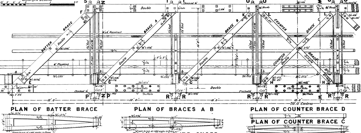
 All the diagonals and principals in the Allan truss are placed at the same angle, which distinguishes them from the Bennett and McDonald trusses. While Dare and de Burgh trusses always have square panels (height and length are equal, so diagonals are at a 45 degree angle), Allan trusses generally have rectangular panels which are higher than they are long.
As with the later truss types, counterbraces are only provided in the middle panel of the Allan truss, and the cross girders are only provided at panel points (no secondary cross girders).
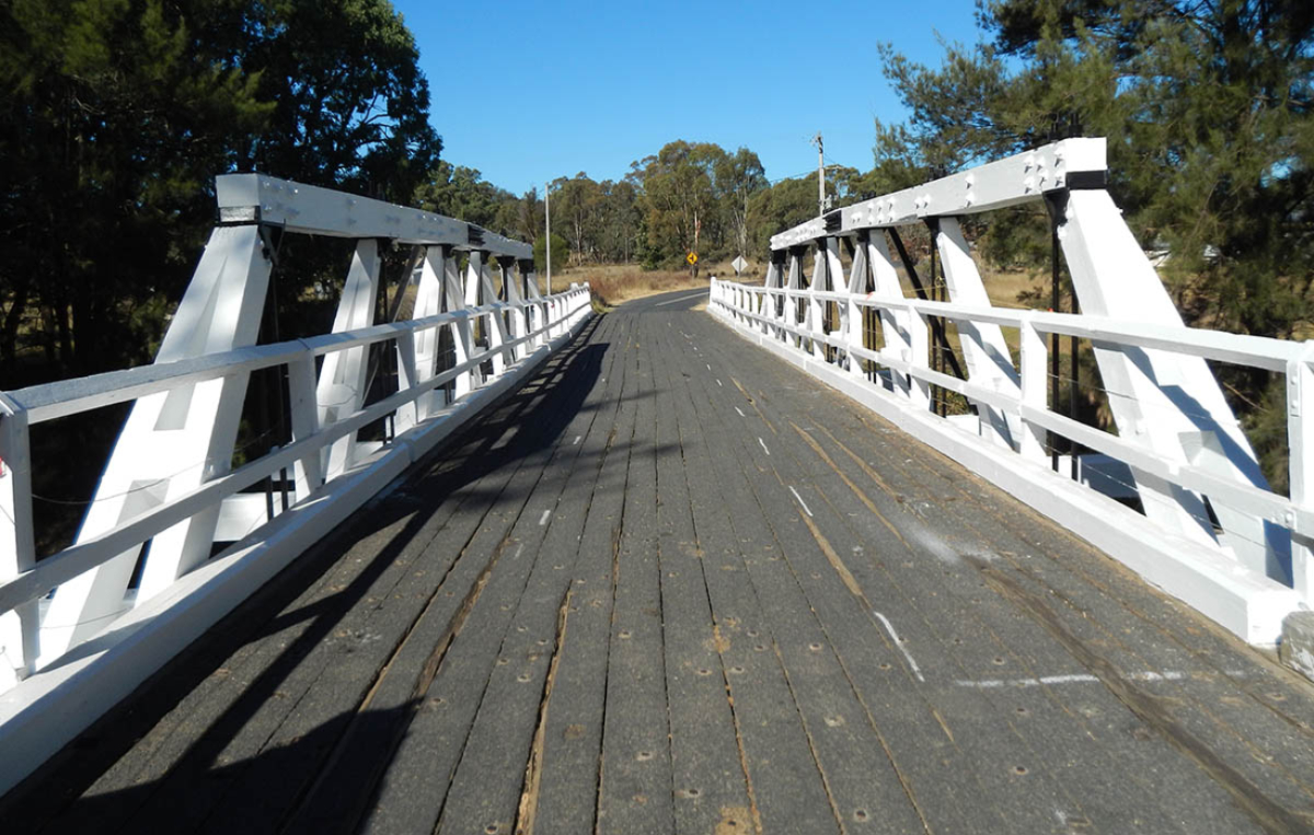
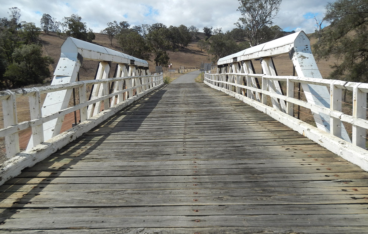 Source: Amie Nicholas, April 2013 (left) August 2013 (right).
 All timber members consist of two timber flitches. Principals, diagonals and top chords consist of two flitches bowed around timber spacers to prevent warping and twisting. The bowing of the timbers is one of the features that distinguishes the Allan truss from the Dare truss. The bottom chord detailing is unique to the Allan truss, consisting of two straight timber flitches with a gap to allow drainage, maintenance and air flow (see diagram below.
 Source: Drawn by Jack Pulczynski for Amie Nicholas.
 Instead of using lots of bolts to transfer the tension force in the bottom chord, as was the theory behind the laminated timber bottom chord used in the Bennett and McDonald truss, the Allan truss makes use of a special splice invented and tested by Allan to take the load.
Wrought-iron tension rods are typical of all the timber truss road bridges. In the Allan truss, they are located in pairs on either side of cross girders, passing through the space between the two flitches of the chords, eliminating bored holes through chords. The tension rods are designed in two sizes, with the larger tension rods located towards the ends of the spans.
Cast-iron shoes are typical of all the timber truss road bridges. In the Allan truss, these shoes are provided at the top and bottom of all diagonal members. The horizontal forces from the principals and diagonals are transferred through shear lugs cut into the chords.
 Source: Drawn by Jack Pulczynski for Amie Nicholas.
 References
[2]Richard Raxworthy, The Unreasonable Man, Sydney: Hale and Iremonger, 1989, p 24.
[3]Percy Allan, “Timber Bridge Construction in New South Wales”, 1895, pp I-VI.
[4]Percy Allan, “Timber Bridge Construction in New South Wales”, 1895, p XIV.
[5]Thomas Pope, A Treatise on Bridge Architecture, New York: Alexander Niven, 1811, p 284.
[6]Percy Allan, “Timber Bridge Construction in New South Wales”, 1895, p VIII.
[7]Percy Allan, “Timber Bridge Construction in New South Wales”, 1895, p XVI.
[8]Henry Harvey Dare, “Recent Road-Bridge Practice in NSW”, p 388.
[9]Percy Allan, “Timber Bridge Construction in New South Wales”, 1895, p VII.
[10]P. Allan, “Highway Bridge Construction II”, Industrial Australian and Mining Standard, 21-08-1924, p 285.
[11]“Correspondence on Swing Bridges”, Minutes of Proceedings of the Institution of Civil Engineers, 16 April 1907, p 88.
[12]Percy Allan, “Timber Bridge Construction in New South Wales”, 1895, pp VI-VII.
[13]Annual Report of the Department of Public Works to the Legislative Assembly of NSW, 1894, p 72.
[14]Percy Allan, “Timber Bridge Construction in New South Wales”, 1895, pp IV-V.
[15]Rex Glencross-Grant, ‘The evolution of large-truss road bridges in NSW, Australia’ Proceedings of the Institution of Civil Engineers, Engineering History and Heritage 165 May 2012 Issue EH2, p 101.
[16]Percy Allan, “Timber Bridge Construction in New South Wales”, 1895, p III.